ER-model. The concept of relationship. The relationship capacity. Types of relationships. Examples
It is recommended that before studying this topic you should familiarize yourself with the following topics:
- The concept of ER-model. The concept of entity. Attributes. Attribute type
- Entity subtypes. Supertype. Example. Advantages and disadvantages of using subtypes of entities
Contents
- 1. What is the relationship in the ER-model? Example
- 2. How are relationships designated?
- 3. What types of relationships are distinguished in the ER-model?
- 4. An example of a one-to-many relationship – 1:M
- 5. What means the “power of relationship” term? Example
- 6. An example of a many-to-many relationship – M:N
- 7. What is the characteristic difference of the type of one-to-one connection 1:1 in comparison with other types?
- 8. What are the features of the implementation of the “many-to-many” relationship or M:N? How to implement a “many-to-many” relationship? Example
- Related topics
Search other websites:
1. What is the relationship in the ER-model? Example
A relationship can be established between two entities. Relations between entities are characterized by a verb that can be used to interact between them. Relation is a kind of relationship between two types of entities.
For example. The above example demonstrates the definition of the relationship between the types of entities Student, Subject, Group.
The student studies a subject – the verb “studies” is highlighted.
A student is studying in a group – the verb “studying” is highlighted.
2. How are relationships designated?
In the ER model, relationships are denoted as a rhombus. Inside the rhombus is indicated a verb that defines the nature of the interaction between the types of entities.
3. What types of relationships are distinguished in the ER-model?
Between entity types, the following 3 types of relationships are distinguished:
- “one-to-one” or 1:1. This means that only one instance of another entity can correspond to one instance of a given entity;
- “one-to-many” or 1:M. This means that one instance of an entity can correspond to any number (M) of instances of another entity. If the value of the maximum number of copies is known, then this value is indicated instead of the symbol M;
- “many-to-many”, or M:N. This means that several instances of one entity may correspond to several instances of another entity.
4. An example of a one-to-many relationship – 1:M
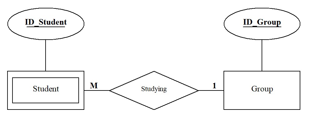
Figure 1 shows a fragment of the ER-model, which demonstrates the relationship between the Student and Group entity types.
Figure 1. Relationship between Student and Group entities types
The above figure shows two types of entities, Student and Group. There is a connection between the types of entities Student and Group, as the student is studying in a group (a rhombus with the text “studies”).
There may be many students in a group. A student can study only in one group, in two or more groups a student cannot study. Therefore, in the figure, the type of connection is designated as 1:M, which means “one-to-many”.
Designation M is located near the Student type of the entity (many students), designation 1 is located near the Group entity (one group). This means that the student is in a subordinate state to the group in which he is studying.
5. What means the “power of relationship” term? Example
The power of relationship is the maximum number of specific instances of entities that can be used for a given connection. The relationship power equals 5, says that in this connection no more than 5 different instances of entities can be used. Or, in other words, no more than 5 different values.
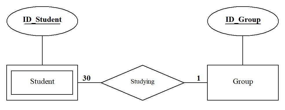
For example. The student is studying in a group. You can establish a 1:30 relationship between the student and group entity types, as shown in Figure 2. The number 30 means that no more than 30 students can study in a group.
Figure 2. The relationship between entities types Student and Group
If the number of entity instance values is arbitrary, then the relationship power is most often represented by the symbol M or by the sign ∝ (infinity).
The use of specific numerical values in relationship power is convenient when developing software, since it is possible to better implement data structures knowing their maximum size.
6. An example of a many-to-many relationship
Let two types of entities be given: Student and Subject. If a student (the type of entity Student) studies a certain subject (entity type of Subject), the connection can be displayed on the ER-model as shown in Figure 3.
Figure 3. Displaying a many-to-many relationship
In Figure 3, the symbols M and N denote the type of many-to-many relationship. This type of communication is chosen, since one student can study several (many) subjects, and, conversely, several students can study one subject.
7. What is the characteristic difference of the type of one-to-one connection 1:1 in comparison with other types?
The type of one-to-one relationship 1:1 differs from other types of communication in that it can be replaced by an attribute. When designing a database, the developer, at his own discretion, must decide whether to use the 1:1 connection type, or whether it is sufficient to replace it with an attribute. It all depends on the specifics of the problem being solved.
8. What are the features of the implementation of the “many-to-many” relationship or M:N? How to implement a “many-to-many” relationship? Example
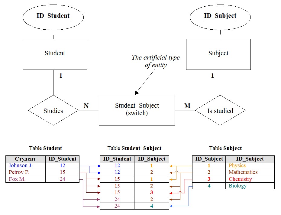
A many-to-many relationship is difficult to implement programmatically, since relational databases support a one-to-many relationship. To solve this problem, the database developer creates an artificial entity type that acts as a switch between the two main entities.
Example. For the two types of entities Student and Subject, you can implement an artificial type of entity, as shown in Figure 4.
Figure 4. Implementing a many-to-many relationship or M:N
In the above figure, the entity-switch contains two attributes that are foreign keys. One attribute is associated with the Student subtype of the entity. The second attribute is associated with a subtype of the Subject entity. An approximate implementation of the corresponding relational tables is also displayed. The Subject_Student table is an additionally created table that displays an artificial type of entity that performs the functions of a switch.
To provide better visibility of the above scheme, a simplified version is often implemented, which is shown in Figure 5. In this case, the artificial type of the entity is depicted as a rhombus inscribed in a rectangle. 
Figure 5. Implementing a simplified version of an artificial entity type on the ER-diagram


